A well-designed gating system is a perquisite for achieving perfect casting. The key objective of a gating system is to ensure smooth and complete flow of molten metal from ladle to the casting cavity.
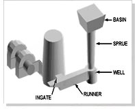
Elements of gating system Elements of gating systemThe main components include pouring basin, sprue, well, runner and ingate. Gating systems can be classified based on the position of the parting plane and also on the basis of ingate position as follows,
- i) Horizontal systems- Suitable for flat castings filled under gravity and commonly used in sand casting of ferrous metals and gravity die casting of non-ferrous metals.
- ii) Vertical systems- Suitable for tall castings and used in high pressure sand and shell mold and die casting processes.
 iii) Top gating systems- wherein the molten metal enters at the top of the casting promoting directional solidification from bottom to top of the casting.
- iv) Bottom gating systems- wherein the molten metal enters from the bottom and fills the mold slowly with minimal
- v) Middle gating systems- these combine the features of top and bottom systems.disturbances.
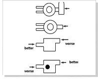
The number and position of ingate(s) is very important in designing the gating systems. The diagram given below describes the different considerations in the channel layout in horizontal gating system with side ingates.
Heuristics for ingate location
- i) Side feeders- When side feeders are used their efficiency can be improved by filling the first stream of hot molten metal through ingates, thereby reducing the fettling effort and subsequent marks on the casting.
- ii) Thick sections - This allows molten metal to flow to other sections with minimal cooling reducing breakage during fettling of ingates.
- ii) Tiii) Clear path - In case of sand casting it is essential to allow the metal to flow with minimal obstructions or direction changes to curb turbulence. In such systems ingates should never be placed opposite to a core.
- iv) Low free fall - here the ingates are located where the free fall of molten metal in the mold cavity is low thereby minimizing oxidation and erosion at the point of impact.
It is also essential to use adequate number of ingates ensuring that the distance of flow between the ingate and any point filled by that ingate is always less than the fluidity distance. Usually the sprue directs the flow of metal from the basin to the runners and the ingates. The location of sprues depends on the following factors,
- i) Flow distance - It must minimize the total flow distance with the gating channel to give maximum yield and minimum heat loss.
- ii) Heat concentration - It must be located away from hot spots in the casting
- iii) Mold layout - It should be positioned to minimize the size of the bounding box, which encloses the entire casting.
- Hick sections- This allows molten metal to flow to other sections with minimal cooling reducing breakage during fettling of ingates.
Optimal Filling Time
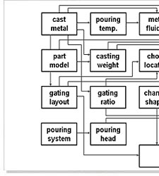
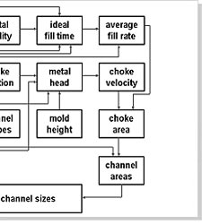
Filling time is very crucial in casting as it decides the final quality of product. A slow fill gives cold shuts and misruns while a fast fill can lead to solid and gaseous inclusions. The ideal filling time is a function of cast metal, weight, minimum section thickness and pouring temperature and can be expressed as, tf = K0 (Kf Lf / 1000) ( Ks + Kt t / 20 ) ( Kw W )P
Where tf is the casting time, W is the weight in kg, t is the section thickness in mm and Lf is the fluidity length in mm, whereas K0, Kf , Ks , Kt , Kw are all coefficients. The value of these coefficients can be set to achieve a perfect metal-process combination in specific castings.
The velocity of molten metal also crucial role in deciding the optimal filling time. The velocity usually varies within the gating channels and the mold cavity. It depends majorly on two factors,
- Metallostatic pressure
- Gating ratio
Gating Element Design
A gating system is designed to fill the casting in prescribed time keeping a constant level of liquid metal in the basin to achieve a controlled flow rate via the choke, a small cross section in system that regulates the flow rate.
The dimensions and shape of different elements in the gating systems is determined as follows,


- i) Sprue - It is a circular cross-section minimizing turbulence and heat loss and its area is quantified from choke area and gating ratio. Ideally it should be large at top and small at bottom.
- ii) Sprue well : It is designed to restrict the free fall of molten metal by directing it in a right angle towards the runner. It aids in reducing turbulence and air aspiration. Ideally it should be shaped cylindrically having diameter twice as that of sprue exit and depth twice of runner.
- iii) Runner - Mainly slows down the molten metal that speeds during the free fall from sprue to the ingate. The cross section are of a runner should be greater than the sprue exit. It should also be able to fill completely before allowing the metal to enter the ingates. In systems where more than one ingate is present, it is recommended that the runner cross section area must be lowered after each ingate connection to ensure smooth flow.
- iv) Ingate : It directs the molten metal from the gating system to the mold cavity. It is recommended that ingate should be designed to reduce the metal velocity; they must be easy to fettle, must not lead to a hot spot and the flow of molten metal from the ingate should be proportional to the volume of casting region.
Different combinations of gating system designs and mold filling are carried out to completely eliminate filling defects. A gating system can be assessed using the following criteria,
- i) Mold filling time -The actual mold filling time must be close to the optimal filling time of the gating system. This can be expressed as, CG1 = 1 - ( | tf-actual - tf-optimal | ) / tf-optimal
- ii) Ingate velocity : The velocity of molten metal emerging from the ingate must be as low as possible to minimize turbulence. It can be expressed as, CG2 = 1 - (Vingate / Vcritical)
- iii) Impingement -Mold erosion is caused by the velocity and direction of the first stream of molten metal emerging from the ingate and striking the mold face. A fast stream should be avoided and can be expressed as, CG3 = Vimp-limit / (Vimp (nimp. nf))
- iv) Gating yield -The volume of the gating system must be minimized to increase the yield. The criterion is given by: CG4 = Nc vc / (Nc vc + vg)
- v) Fettling - The ingate size must be small in comparison to the connected part of casting to avoid breakage and cracks.
Validation of gating design
The gating design can be validated using the following techniques,
- i) Shop floor trials - Samples are produced using the actual materials and process that would be finally employed. These are observed for surface, sub-surface and internal quality and destructive and non-destructive testing methods.
- ii) High-speed radiography - The mold filling phenomenon is recorded using a high speed x-ray camera and observed of any defects.
- iii) Open mold - In this a portion of cope above casting cavity is cut and a flow of molten metal stream form ingate and gradual filling of the mold is recorded using a video camera.
- iv) Contact wire sensing - In this contact wires are placed in different parts of the mold and when the metal touches a particular wire, the metal flow gets recorded by a multichannel recorder.
- v) Water in transparent mold - Flow of water in a transparent mold is a very useful tool. Addition of color marker, oil droplets can help in better visualization and recording velocities in different sections.
